
why flanged rubber expansion joints with integral rubber flanges require split (two-piece) backing flanges.
author: Liuna
2026-04-08

Why Do Flanged Rubber Expansion Joints with Vulcanized Flanges Require Split Backing Flanges?
In the field of industrial piping systems, the rubber expansion joint is an indispensable component for absorbing vibration, compensating for thermal movement, and reducing mechanical noise. Among the various configurations available, the flanged type with integral rubber flanges—often referred to as "vulcanized flanged" or "full-rubber flanged" expansion joints—is one of the most widely used designs. However, a common question that arises among engineers, procurement specialists, and maintenance personnel is: why do these expansion joints always require split (two-piece) backing flanges, rather than standard one-piece flanges?
The answer lies in a combination of manufacturing constraints, installation practicality, sealing performance, and long-term operational reliability. This article explores each of these factors in detail.
Manufacturing and Assembly Constraints
The primary and most fundamental reason for using split backing flanges is purely mechanical: the rubber flange itself physically prevents a one-piece flange from being installed. In a vulcanized flanged expansion joint, the rubber body is molded with its end faces turned outward to form a flange profile that matches standard piping flange dimensions. The elastomer material, reinforced with internal fabric plies and steel wire cord, is chemically bonded and vulcanized into this shape during the manufacturing process. This creates a continuous, leak‑tight rubber sealing face at each end.
Because this rubber flange is an integral part of the joint body, the end face is completely sealed and closed. It is impossible to slide a solid, one‑piece metal flange ring over the joint from the outside, as the rubber flange blocks the path. The only practical solution is to use a backing flange that is split into two halves—or sometimes into four segments for very large diameters—so that the pieces can be assembled around the neck of the joint, directly behind the rubber flange, after the joint has been manufactured. Without this split construction, the flange simply cannot be fitted onto the joint body.
Sealing Effectiveness and Pressure Distribution
Beyond the installation necessity, split backing flanges play a critical role in achieving a reliable seal. When the expansion joint is bolted between two pipe flanges, the split backing flanges act as load‑bearing plates. As the bolts are tightened, these metal rings transfer the compressive force uniformly across the full face of the rubber flange. This even pressure distribution ensures that the elastomer deforms slightly and conforms perfectly to the mating pipe flange surface, creating a self‑energizing seal that improves as internal pressure increases. Attempting to use a standard one‑piece flange in this application would not only be physically impossible to assemble but would also fail to provide the correct loading pattern on the rubber flange, often leading to uneven compression, localized stress concentrations, and eventual leakage.
Pull‑Out Resistance and Anchoring
Split backing flanges also provide superior resistance to axial pull‑out forces. During pipeline operation, internal pressure generates significant thrust forces that tend to separate the expansion joint from its connected pipe ends. The split flanges are positioned directly behind the rubber flange's reinforcing ring or bead, which is firmly anchored into the elastomer body. When tension is applied, the metal split flanges engage this reinforced shoulder, effectively preventing the rubber flange from being pulled out from between the pipe flanges. This anchoring mechanism is far more reliable than other connection methods, such as grooved or clamping types, especially in high‑pressure or high‑vibration environments. The split design allows the metal flange to be perfectly matched to the rubber flange's geometry, ensuring that the load is carried by the full circumference of the joint rather than by localized points.
Ease of Installation and Maintenance
Practical field considerations also favor the split flange design. Two‑piece backing flanges are significantly easier to handle, align, and install compared to a hypothetical solid flange of equivalent size. The halves can be placed around the joint neck independently, allowing the bolt holes to be rotated and adjusted to match the bolt pattern of the existing pipe flanges without needing to rotate the entire heavy expansion joint. This is particularly valuable in confined spaces or when the joint must be installed in an existing pipeline with limited clearance. Additionally, during maintenance or replacement, the split flanges can be removed without dismantling the entire piping assembly, saving both time and labor costs.
Avoidance of Welding Defects
Historically, some expansion joints relied on welded metal flanges directly attached to the rubber body through steel retaining rings—a method that often introduced weak points. The vulcanized flange combined with split backing flanges eliminates the need for welding on the elastomer‑to‑metal interface. This reduces the risk of stress cracking, corrosion, and fatigue failure at weld points, and ensures that the entire joint remains homogeneous and flexible. The split flange design thus supports a longer service life and greater operational safety, particularly in cyclic thermal and pressure conditions.
Conclusion
In summary, the requirement for split (two‑piece) backing flanges on vulcanized rubber expansion joints is driven by multiple interconnected factors. The physical impossibility of installing a one‑piece flange after the rubber flange is molded makes the split design an absolute necessity. Beyond that, split flanges ensure uniform sealing pressure, provide strong pull‑out resistance, simplify installation and maintenance, and eliminate welding‑related failure risks. For engineers specifying these joints, understanding this design rationale is essential for selecting the correct hardware, ensuring proper assembly, and guaranteeing long‑term, leak‑free performance of the piping system.
In the field of industrial piping systems, the rubber expansion joint is an indispensable component for absorbing vibration, compensating for thermal movement, and reducing mechanical noise. Among the various configurations available, the flanged type with integral rubber flanges—often referred to as "vulcanized flanged" or "full-rubber flanged" expansion joints—is one of the most widely used designs. However, a common question that arises among engineers, procurement specialists, and maintenance personnel is: why do these expansion joints always require split (two-piece) backing flanges, rather than standard one-piece flanges?
The answer lies in a combination of manufacturing constraints, installation practicality, sealing performance, and long-term operational reliability. This article explores each of these factors in detail.
Manufacturing and Assembly Constraints
The primary and most fundamental reason for using split backing flanges is purely mechanical: the rubber flange itself physically prevents a one-piece flange from being installed. In a vulcanized flanged expansion joint, the rubber body is molded with its end faces turned outward to form a flange profile that matches standard piping flange dimensions. The elastomer material, reinforced with internal fabric plies and steel wire cord, is chemically bonded and vulcanized into this shape during the manufacturing process. This creates a continuous, leak‑tight rubber sealing face at each end.
Because this rubber flange is an integral part of the joint body, the end face is completely sealed and closed. It is impossible to slide a solid, one‑piece metal flange ring over the joint from the outside, as the rubber flange blocks the path. The only practical solution is to use a backing flange that is split into two halves—or sometimes into four segments for very large diameters—so that the pieces can be assembled around the neck of the joint, directly behind the rubber flange, after the joint has been manufactured. Without this split construction, the flange simply cannot be fitted onto the joint body.
Sealing Effectiveness and Pressure Distribution
Beyond the installation necessity, split backing flanges play a critical role in achieving a reliable seal. When the expansion joint is bolted between two pipe flanges, the split backing flanges act as load‑bearing plates. As the bolts are tightened, these metal rings transfer the compressive force uniformly across the full face of the rubber flange. This even pressure distribution ensures that the elastomer deforms slightly and conforms perfectly to the mating pipe flange surface, creating a self‑energizing seal that improves as internal pressure increases. Attempting to use a standard one‑piece flange in this application would not only be physically impossible to assemble but would also fail to provide the correct loading pattern on the rubber flange, often leading to uneven compression, localized stress concentrations, and eventual leakage.
Pull‑Out Resistance and Anchoring
Split backing flanges also provide superior resistance to axial pull‑out forces. During pipeline operation, internal pressure generates significant thrust forces that tend to separate the expansion joint from its connected pipe ends. The split flanges are positioned directly behind the rubber flange's reinforcing ring or bead, which is firmly anchored into the elastomer body. When tension is applied, the metal split flanges engage this reinforced shoulder, effectively preventing the rubber flange from being pulled out from between the pipe flanges. This anchoring mechanism is far more reliable than other connection methods, such as grooved or clamping types, especially in high‑pressure or high‑vibration environments. The split design allows the metal flange to be perfectly matched to the rubber flange's geometry, ensuring that the load is carried by the full circumference of the joint rather than by localized points.
Ease of Installation and Maintenance
Practical field considerations also favor the split flange design. Two‑piece backing flanges are significantly easier to handle, align, and install compared to a hypothetical solid flange of equivalent size. The halves can be placed around the joint neck independently, allowing the bolt holes to be rotated and adjusted to match the bolt pattern of the existing pipe flanges without needing to rotate the entire heavy expansion joint. This is particularly valuable in confined spaces or when the joint must be installed in an existing pipeline with limited clearance. Additionally, during maintenance or replacement, the split flanges can be removed without dismantling the entire piping assembly, saving both time and labor costs.
Avoidance of Welding Defects
Historically, some expansion joints relied on welded metal flanges directly attached to the rubber body through steel retaining rings—a method that often introduced weak points. The vulcanized flange combined with split backing flanges eliminates the need for welding on the elastomer‑to‑metal interface. This reduces the risk of stress cracking, corrosion, and fatigue failure at weld points, and ensures that the entire joint remains homogeneous and flexible. The split flange design thus supports a longer service life and greater operational safety, particularly in cyclic thermal and pressure conditions.
Conclusion
In summary, the requirement for split (two‑piece) backing flanges on vulcanized rubber expansion joints is driven by multiple interconnected factors. The physical impossibility of installing a one‑piece flange after the rubber flange is molded makes the split design an absolute necessity. Beyond that, split flanges ensure uniform sealing pressure, provide strong pull‑out resistance, simplify installation and maintenance, and eliminate welding‑related failure risks. For engineers specifying these joints, understanding this design rationale is essential for selecting the correct hardware, ensuring proper assembly, and guaranteeing long‑term, leak‑free performance of the piping system.
Why Metal Bellows Expansion Joints for Flue & Air Ducts Are Low Pressure Rated?
Mandatory Installation Conditions of Limit Tie Rods for Rubber Expansion Joints
Related Article

Internal‑pressure bellows: medium inside bellows, inner liner inside, tie‑rods needed for large displacement.
External‑pressure bellows: medium outside bellows, nested sleeve structure, good anti‑instability, tie‑rods normally not required.
External‑pressure bellows: medium outside bellows, nested sleeve structure, good anti‑instability, tie‑rods normally not required.
Internal‑pressure vs External‑pressure Metal Bellows Expansion Joints ?

NBR rubber expansion joints fail in high-temperature thermal oil systems because thermal oil runs above 300°C, while NBR can only handle ~90–140°C. This extreme heat causes rapid oil-swelling (softening and seal failure) and thermo-oxidative aging (hardening and cracking). The joint quickly fails, leading to thermal oil leaks and fire hazards. Use stainless steel or specially insulated expansion joints instead.
Why NBR Rubber Expansion Joints Cannot Be Used in High-Temperature Thermal Oil Systems
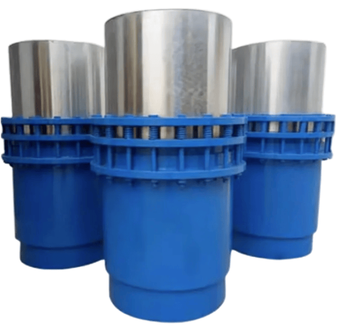
When selecting pipeline expansion components, many engineering purchasers and designers notice a common phenomenon: stock sleeve expansion joints on the market mostly adopt 200 mm as the basic axial compensation stroke, while the single-unit compensation capacity of conventional bellows expansion joints generally ranges from 50 mm to 120 mm. This difference is jointly determined by product principles, application scenarios and production economy.
Why Do Sleeve Expansion Joints Generally Start With a Compensation Capacity of 200 mm?

The counter-flange inner diameter is smaller than the expansion joint's flange bore to: fully compress the rubber sealing surface and prevent leaks, avoid sharp edges cutting the rubber during vibration, and act as a retaining ring to prevent pull-out accidents. This protects the rubber and ensures safety—always use matching flanges during installation.
Technical Explanation: Why Is the Inner Diameter of the Matching Counter-Flange Often Smaller Than That of the Rubber Expansion Joint's Own Flange?