
Technical Explanation: Why Is the Inner Diameter of the Matching Counter-Flange Often Smaller Than That of the Rubber Expansion Joint's Own Flange?
author: LIUNA
2026-03-18

I. Core Objective: Protecting the Vulnerable Rubber Sealing Surface
The flange plate of a rubber expansion joint (typically made of Q235B carbon steel or ductile iron) and its rubber body are integrally molded through vulcanization. What actually provides the sealing function is not the back face of the metal flange plate, but the ring-shaped "sealing surface" extending from the rubber body.
The flange plate of a rubber expansion joint (typically made of Q235B carbon steel or ductile iron) and its rubber body are integrally molded through vulcanization. What actually provides the sealing function is not the back face of the metal flange plate, but the ring-shaped "sealing surface" extending from the rubber body.
If the counter-flange inner diameter is too large: When the bolts are tightened, the inner edge of the counter-flange will not be able to completely cover and compress the rubber sealing surface. The uncovered rubber portion will be exposed to the pipeline medium and, under pressure, will undergo creep or deformation, resulting in insufficient sealing specific pressure and consequently causing leakage.
Correct approach (smaller/matching inner diameter): A smaller counter-flange inner diameter ensures that the entire inner flat surface of the metal flange firmly presses against the rubber sealing surface, forming a stable sealing zone.
II. Preventing the Risk of "Cutting" the Rubber by Sharp Edges
In pipeline systems, commonly used flange standards (such as GB/T 9119, HG/T 20592) include flat-face flanges (FF) and raised-face flanges (RF), depending on the pressure rating. For raised-face flanges, the inner edge of the raised sealing face often has machined chamfers or sharp corners.
In pipeline systems, commonly used flange standards (such as GB/T 9119, HG/T 20592) include flat-face flanges (FF) and raised-face flanges (RF), depending on the pressure rating. For raised-face flanges, the inner edge of the raised sealing face often has machined chamfers or sharp corners.
Potential risk: If the counter-flange inner diameter is smaller than that of the expansion joint flange, it generally means the counter-flange is thicker or its inner edge is closer to the center. If this inner edge is not smoothly finished, under pipeline vibration or axial displacement caused by thermal expansion and contraction, the sharp metal edge will repeatedly rub against or cut the rubber body like a knife.
Design intention: Standard specifications require that the counter-flange inner diameter must not exceed the diameter of the rubber body's root, so as to avoid wear and rupture of the rubber due to repeated deformation from hard contact with metal.
III. Structural Safeguard Against "Pull-Out" Accidents
The operating condition of a rubber expansion joint is not static. During pump startup or pipeline thermal expansion, the expansion joint withstands significant axial tensile forces and the blind-end pressure generated by internal medium pressure.
The operating condition of a rubber expansion joint is not static. During pump startup or pipeline thermal expansion, the expansion joint withstands significant axial tensile forces and the blind-end pressure generated by internal medium pressure.
Mechanical principle: The metal flange bore of the rubber expansion joint provides the passage for the medium. If the counter-flange inner diameter is larger than the expansion joint's inner diameter, the internal medium pressure will generate an outward thrust, and the rubber body may bulge outward beyond the flange due to the lack of a metal retaining plate to "limit" its movement.
Safety barrier: The counter-flange with a smaller inner diameter effectively acts as a "retaining ring". It effectively restricts axial movement of the rubber body under extreme tensile forces, preventing the rubber body from being pulled out from the flange root, thereby averting major pipeline accidents.
IV. Standard Matching Requirements in Engineering Practice
According to the industry standard for flexible rubber joints (CJ/T 208-2005) and installation atlases (such as 03S403), the following explicit provisions apply to the selection of counter-flanges:
According to the industry standard for flexible rubber joints (CJ/T 208-2005) and installation atlases (such as 03S403), the following explicit provisions apply to the selection of counter-flanges:
Prioritize the Use of Butterfly Valve Special Flanges: In modern industrial design, manufacturers generally recommend matching with butterfly valve special flanges whose inner diameter matches the expansion joint's inner diameter. This type of flange has an inner bore machined precisely to the nominal diameter, ensuring adequate sealing compression surface while avoiding step gaps.
Add a Spacer Ring for Standard Flanges: If only standard flat-weld flanges are available on site, and the counter-flange inner diameter is indeed larger than that of the expansion joint, then a metal retaining ring or asbestos gasket with a matching inner diameter must be installed between the flanges to fill the gap and protect the rubber sealing surface.
Why Do Sleeve Expansion Joints Generally Start With a Compensation Capacity of 200 mm?
Single vs Double Bellows Expansion Joints: Application Conditions
Related Article

NBR rubber expansion joints fail in high-temperature thermal oil systems because thermal oil runs above 300°C, while NBR can only handle ~90–140°C. This extreme heat causes rapid oil-swelling (softening and seal failure) and thermo-oxidative aging (hardening and cracking). The joint quickly fails, leading to thermal oil leaks and fire hazards. Use stainless steel or specially insulated expansion joints instead.
Why NBR Rubber Expansion Joints Cannot Be Used in High-Temperature Thermal Oil Systems
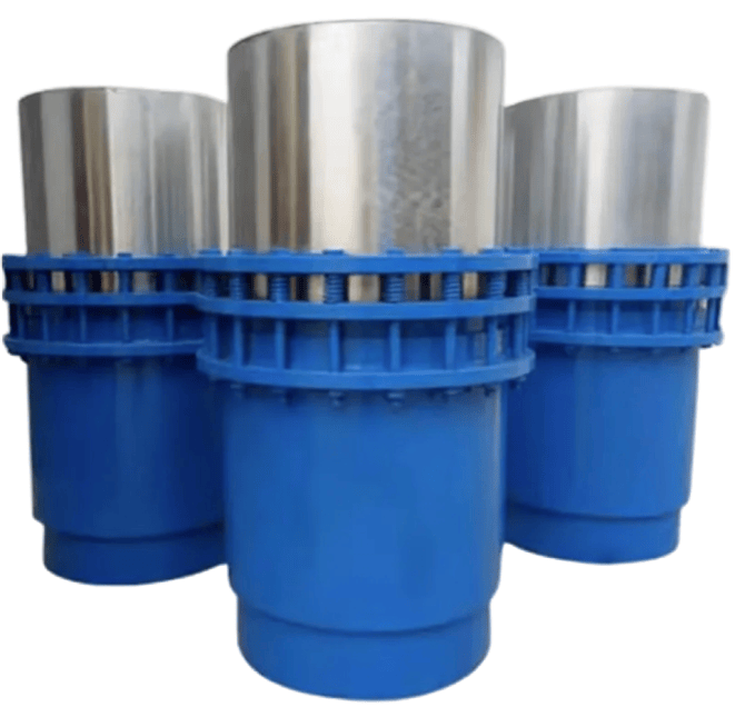
When selecting pipeline expansion components, many engineering purchasers and designers notice a common phenomenon: stock sleeve expansion joints on the market mostly adopt 200 mm as the basic axial compensation stroke, while the single-unit compensation capacity of conventional bellows expansion joints generally ranges from 50 mm to 120 mm. This difference is jointly determined by product principles, application scenarios and production economy.
Why Do Sleeve Expansion Joints Generally Start With a Compensation Capacity of 200 mm?


Flue duct metal expansion joints are low-pressure type:
1.Flue systems work under micro pressure.
2.Large rectangular bellows deform easily under high pressure.
3.High pressure creates huge thrust to break supports.
4.High flue temperature weakens metal.
5.Thin low-pressure bellows offer flexible compensation at low cost.
Small round pipes support higher pressure; fabric joints suit ultra-low pressure ducts.
1.Flue systems work under micro pressure.
2.Large rectangular bellows deform easily under high pressure.
3.High pressure creates huge thrust to break supports.
4.High flue temperature weakens metal.
5.Thin low-pressure bellows offer flexible compensation at low cost.
Small round pipes support higher pressure; fabric joints suit ultra-low pressure ducts.
Why Metal Bellows Expansion Joints for Flue & Air Ducts Are Low Pressure Rated?