
Operating Conditions for Using Sleeve Compensators Instead of Bellows Expansion Joints
author: Zhimin Yang
2025-07-01

Operating Conditions for Using Sleeve Compensators Instead of Bellows Expansion Joints

VS

Below are typical scenarios where sleeve compensators are preferred over bellows expansion joints, categorized by displacement characteristics, pressure/size parameters, operational risks, maintenance and cost factors, along with critical limiting caveats.
1. Long Straight Pipe Runs Requiring Large Axial Compensation
Bellows expansion joints typically only deliver axial compensation of dozens of millimeters per unit. For long-distance heating mains, plant steam/hot water straight pipelines and large-diameter water/oil transmission lines, thermal elongation of a single pipe segment can reach 100+ mm.
• Frequent bellows installation demands numerous anchor/guide supports, driving up total cost and increasing failure points.
• Sleeve compensators rely on sliding telescoping, achieving 200–500 mm large axial travel per unit, drastically cutting installation quantity. Their rigid structure avoids bellows risks like buckling, bulging and fatigue cracking; performance is superior under high-temperature steam and repeated thermal cycling.
• Core prerequisite: Displacement is pure axial, with negligible lateral/angular deflection or foundation settlement; proper guide supports must maintain coaxial alignment to prevent jamming and seal wear from side loads.
2. Large Diameter & Medium-to-High Pressure Service Where Bellows Fail or Become Prohibitively Expensive
Applicable for pipes DN500 and above, operating at 1.6–4.0 MPa (heating primary networks, power plant main steam/circulating water, metallurgical high-temperature process piping):
• Large thin-walled bellows are difficult to fabricate, have skyrocketing material costs, and suffer column/planar buckling and stress corrosion cracking (critical risk in chloride-containing water).
• Sleeve compensators use thick pressure-bearing cylindrical bodies with stable pressure resistance, lower carbon steel material costs, and better resistance to chloride corrosion and medium erosion.
3. Harsh Environments That Rapidly Damage Thin Bellows
1. Mechanical impact/external compression (vehicle loads, backfill soil pressure): Thin bellows crush or tear easily; robust sleeve bodies resist impact and squeezing.
2. Media with solid particles/abrasives (ash water, slag removal water): Debris accumulates in bellows troughs causing erosive perforation; smooth sliding sleeve surfaces + repackable packing can be maintained/replaced on-site, far more repairable than bellows (which require full cutout replacement once ruptured).
3. Continuous high-temperature cycling/frequent start-stop operation: Bellows fatigue life degrades rapidly from cyclic flexing; sliding sleeves have no elastic fatigue failure modes for stable long service life.
4. Accessible Piping (Aerial/Utility Tunnels) With Planned Routine Maintenance, Targeting Long-Term Economy
Ideal for locations with regular inspection access (overhead lines, plant piping, walkable tunnels) where gland tightening/graphite packing replacement can be performed:
• Low upfront capital cost, online emergency repair capability for minor leaks, lower total lifecycle cost vs. high-cost large bellows and unplanned shutdown risks from bellows rupture.
• Not suitable for deeply buried inaccessible runs, high elevations, sealed confined spaces where maintenance cannot be performed—minor packing leakage cannot be mitigated quickly, so maintenance-free bellows are required here.
Critical Boundaries & Prohibited Use Cases (Do Not Replace Blindly)
1. Elbows, tees, equipment nozzles, sections prone to settlement/seismic lateral/angular displacement: Use hinged/bellows expansion joints; side loads jam sleeves and cause accelerated seal wear and catastrophic leakage.
2. Ultra-clean, high-value, flammable, explosive or toxic media with zero tolerance for minor seepage: Welded sealed bellows are the safer choice.
3. Small diameters (≤DN200), short pipe segments, cramped spaces: Compact, maintenance-free bellows are more practical and cost-effective.
4. Adjacent to pumps/compressors requiring vibration/noise damping: Flexible bellows deliver superior vibration isolation; sliding friction in sleeves amplifies noise and vibration transmission.
Summary
Select sleeve compensators over bellows expansion joints for long straight pure axial piping, large-diameter medium-high pressure service, large required compensation stroke, accessible locations for regular maintenance, and exposure to mechanical impact/abrasion that destroys thin bellows.
Stick with bellows expansion joints for complex routing, inaccessible areas, multi-directional displacement needs, zero-leakage requirements, and vibration/noise reduction applications.
Quick Selection Checklist (English)
Check Item Suitable for Sleeve Compensator Prefer Bellows Expansion Joint
Primary displacement Pure axial only Lateral/angular/combined movement
Pipe size & pressure DN500+, 1.6–4.0 MPa Small bore DN200 and below, low pressure
Compensation demand Large axial travel (≥100 mm) Small displacement, localized flexibility
Operating environment Abrasive media, mechanical impact Clean media, confined/protected layout
Maintenance access Inspectable, repackable on schedule Buried/sealed, no maintenance access
Special requirements Cost focus, pressure stability Zero leakage, vibration damping.
Stick with bellows expansion joints for complex routing, inaccessible areas, multi-directional displacement needs, zero-leakage requirements, and vibration/noise reduction applications.
Quick Selection Checklist (English)
Check Item Suitable for Sleeve Compensator Prefer Bellows Expansion Joint
Primary displacement Pure axial only Lateral/angular/combined movement
Pipe size & pressure DN500+, 1.6–4.0 MPa Small bore DN200 and below, low pressure
Compensation demand Large axial travel (≥100 mm) Small displacement, localized flexibility
Operating environment Abrasive media, mechanical impact Clean media, confined/protected layout
Maintenance access Inspectable, repackable on schedule Buried/sealed, no maintenance access
Special requirements Cost focus, pressure stability Zero leakage, vibration damping.
Tolerance Requirements for Installation Length of Rubber Expansion Joints
Why Must Flanged Rubber Joints Be Fitted with Vacuum Rings?
Related Article

NBR rubber expansion joints fail in high-temperature thermal oil systems because thermal oil runs above 300°C, while NBR can only handle ~90–140°C. This extreme heat causes rapid oil-swelling (softening and seal failure) and thermo-oxidative aging (hardening and cracking). The joint quickly fails, leading to thermal oil leaks and fire hazards. Use stainless steel or specially insulated expansion joints instead.
Why NBR Rubber Expansion Joints Cannot Be Used in High-Temperature Thermal Oil Systems
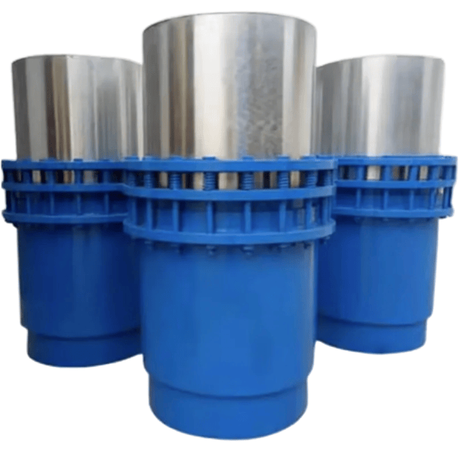
When selecting pipeline expansion components, many engineering purchasers and designers notice a common phenomenon: stock sleeve expansion joints on the market mostly adopt 200 mm as the basic axial compensation stroke, while the single-unit compensation capacity of conventional bellows expansion joints generally ranges from 50 mm to 120 mm. This difference is jointly determined by product principles, application scenarios and production economy.
Why Do Sleeve Expansion Joints Generally Start With a Compensation Capacity of 200 mm?

The counter-flange inner diameter is smaller than the expansion joint's flange bore to: fully compress the rubber sealing surface and prevent leaks, avoid sharp edges cutting the rubber during vibration, and act as a retaining ring to prevent pull-out accidents. This protects the rubber and ensures safety—always use matching flanges during installation.
Technical Explanation: Why Is the Inner Diameter of the Matching Counter-Flange Often Smaller Than That of the Rubber Expansion Joint's Own Flange?
